|
In fire insurance frameworks in which pressure that surpasses the most extreme permitted by NFPA guidelines, needs to be decreased to adequate levels for sprinkler frameworks and a local group of fire-fighters hose valves. For instance, elevated structures frequently require pressure reducing valves. A siphon that is equipped for supplying the minimum satisfactory pressure to the highest level will convey extreme pressure on the lower floors. The decrease of pressure must be given to the lower levels when a building surpasses 15 to 20 stories. 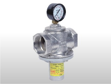 The most widely recognized approach to control pressure is by the utilization of direct-acting pressure reducing valves on each floor. These valves can lessen the overabundance pressure from single-zone gracefully risers and are either customizable or the fixed decrease type. There are again more uncommon and mainly more costly ways to deal with high-pressure control. One methodology like this is to utilize various graceful zones with independent siphon frameworks for each zone. There is another strategy separated from this which is to utilize a single siphon framework that provisions various risers (zones) with the pressure on every riser constrained by an enormous pilot worked pressure reducing valve. This article is focused on direct-acting pressure-reducing valves. Direct-acting pressure reducing valves accompany an extremely basic plan idea however its water-driven execution can likewise be a cycle confusing for the inexperienced framework fashioner. With a touch of understanding of how they work, it will be much simpler to viably apply them in fire frameworks. The nonadjustable PRV is the most basic one. Its key useful parts are the seat and floating stem gathering, the handwheel and the manual stem alongside the cylinder. Within the floating stem, there is a liquid entry that permits the valve outlet pressure to arrive at the top side of the cylinder. The cylinder is constrained descending against a shoulder on the floating stem. The cylinder water-powered zone alongside the seat circle holder pressure-driven zone with the manual stem being in the completely vacant position brings about a net power the shut way to such an extent that the valve works in a self-throttling mode. The throttling degree is determined by the cylinder distance across and the corresponding cylinder within the valve cap. In various renditions, these nonadjustable PRVs are accessible, each with an alternate cylinder breadth for providing the scope of decrease proportions that are required for a few flexibly pressure conditions. With the increase of the cylinder width, the level of throttling increases. Under static conditions, similar to when the sprinkler framework is in typical reserve modem or in situations when a hose spout shutoff is shut, the water-powered territory differential causes the seat to close naturally to and the necessary pressure decrease is maintained. In instances of the flexible direct acting pressure reducing valves, they are somewhat more mind-boggling than the non-movable ones. Notwithstanding all the major utilitarian parts of the nonadjustable valve, it likewise contains a couple of settled pressure springs and a framework to alter the compacted tallness of the springs. The heap which has been created by the pressure springs follows up on the floating stem and seat the other way as the water-powered burden delivered by the cylinder. The spring load is increased, and the heap created by the cylinder is balanced if the change collar is turned toward the path to diminishing the packed stature of the springs. The valve pressure decrease proportion is diminished and the cylinder measurement is decreased successfully. Again by turning the change collar for increasing the spring tallness, the contrary impact is additionally accomplished. Aira Euro Automation is the Best Pressure Reducing Valve Manufacturer in India, Aira has a wide range of pneumatic and manually operated industrial valves. They export their products in more than 20 countries including Gulf countries.
0 Comments
Design Considerations for Water Pressure Reducing Valve (PRV) Stations in Commercial Buildings9/27/2020 Pressure Reducing Valve (PRV) Stations are a significant segment of a water-conveyance framework in a commercial building. The 2015 Uniform Plumbing Code Section 608.2 states that PRVs are required anytime where the framework static pressure surpasses 80 PSI. Ordinarily, this applies to mid-and tall structures when the pressure support required at the ground floor to serve the upper floors in the building is more than 80 PSI. When designing a PRV Station, you should consider the station pressure drop, water stream, and wellbeing gadgets. 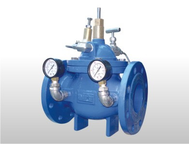 To compute the Pressure Drop over the PRV Station, we need to determine the inlet and outlet pressures. The inlet pressure is determined by the PRV area in the building. The lower the PRV is in the building, the higher the static inlet pressure will be. Commonly, the PRVs are taken care of by a Pressure Boosting System that takes care of the whole building, so the inlet pressure may likewise change a touch of, depending on the interest in the remainder of the building.
The outlet pressure is determined by two components. First is the quantity of floors the PRV Station is serving, and the subsequent factor is whether the station is feeding the floors above or underneath the station. A decent dependable guideline is that each floor will bring about a pressure change of 5 PSI. In the event that the floors took care of by the PRV Station are the floors above, at that point, you would require a higher outlet pressure at the PRV Station (around 65 to 75 PSI) on the grounds that the pressure will drop around 5 PSI each floor higher in the piping. On the off chance that the PRV Station is feeding the floors underneath, the outlet pressure would be lower (around 40 to 50 PSI) in light of the fact that the pressure will increase 5 PSI for each floor lower in the piping. We suggest keeping the pressure drop over any single PRV to under 100 PSI to evade lackluster showing, cavitation, commotion, and valve harm. The water-stream requests of a PRV Station rely upon the number of apparatuses being served by the station and can be determined using Hunter's Curve, which unfortunately doesn't represent the decent variety in the framework request. In the event that the building's water stream is overestimated, PRVs will in general be curiously large and don't perform well at incomplete burden conditions. Combining two valves in corresponding with High and Low Flow Valves assists with keeping the two valves operating within their design conditions overall heap requests. At the point when a Pressure Reducing Valve comes up short, high-pressure water will be permitted to go through the station to the installations downstream. By code, an extension tank or alleviation valve is required downstream of the PRV. We suggest the utilization of an immediate acting alleviation valve, alongside a control framework to close down the water stream. A pressure switch detects the high pressure downstream of the PRV and signs the control board to close the square valve. The control board additionally imparts the caution sign to the building management framework to alarm the building engineers. Likewise, with Level Control Systems, we generally suggest monitoring these alert yields. Aira Euro Automation is a leading Best Pressure Reducing Valve Manufacturer in India, Aira has a wide range of pneumatic and manually operated industrial valves. They export their products in more than 20 countries including Gulf countries. Pressure-controller and temperature controllers speak to extended choices as a solid arrangement. Steam, fluids, and gases stream at high pressures to their most extreme level. At these focuses, a pressure controller or potentially temperature controllers brings down the pressure for wellbeing and effectiveness, and to coordinate the prerequisites of the application. There are three kinds of pressure-reducing valves. Direct-acting. The least difficult of pressure controller or potentially temperature controllers, the immediate acting sort, works with either a level stomach or tangled cries. Since it is independent, it needn't bother with an outside detecting line downstream to work. It is the littlest and generally prudent of the three sorts and is intended for low to direct streams. The exactness of direct-acting pressure controller and temperature controllers is regularly +/ - 10% of the downstream set point.
Inside steered cylinder worked. This sort of pressure controller and temperature controllers consolidates two valves-a pilot and a fundamental valve-in one unit. The pilot valve has a plan like that of the immediate acting valve. The release from the pilot valve follows up on the head of a cylinder, which opens the primary valve. This plan utilizes delta pressure in opening an enormous fundamental valve than could somehow or another be opened legitimately. Subsequently, there is a more noteworthy limit per line size and more prominent precision (+/ - 5%) than with the immediate acting valve. Likewise, with direct-acting valves, the pressure is detected inside, wiping out the requirement for an outside detecting line. Remotely guided. In this sort, twofold stomachs supplant the cylinder administrator of the inside guided plan. This expanded stomach region can open a huge primary valve, permitting a more prominent limit for every line size than the inside directed valve. Likewise, the stomachs are more delicate to pressure changes, and that implies exactness of +/ - 1%. This more noteworthy exactness is because of the area, outer to the valve, of the detecting line, where there is less choppiness. This valve likewise offers the adaptability to utilize various kinds of pilot valves (i.e., pressure, temperature, air-stacked, solenoid, or mixes). Aira Euro Automation is the Best Pressure Reducing Valve Manufacturer in India, Aira has a wide range of pneumatic and manually operated industrial valves. They export their products in more than 20 countries including Gulf countries. Pressure Reducing Valve manufacturer (or Regulator) makes and holds a downstream pressure set point. Moreover, the pilot and the valve are one piece, which assigns it as an "incorporated valve." You'll regularly observe the Pressure Reducing Valve utilized as an attractions regulator or distribution valve on blowers, or to flexibly fuel gas. 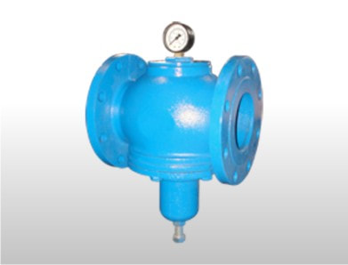 How Does a Pressure Reducing Valve Work?
This valve screens downstream pressure. Turn the jolt on top to modify the set point. This will pack the spring. The spring pushes down on the detecting stomach get together. This positions the pilot plug. Next, the pilot plug permits gas from upstream to stream under the engine valve stomach. The pressure is controlled under this stomach, which positions the unclogger to insure against changes in streaming conditions. In the event that the pressure surpasses the set point, the upstream pressure pushes up on the detecting stomach toget together. This shuts the pilot plug. The underneath of the engine valve stomach vents gas which manages the downstream pressure. This sets a consistent downstream pressure. Since the stomach has a bigger surface region than the unclogger, a similar pressure can hold the valve in a shut position. Pressure-reducing valves (PRVs) maintain secondary, lower pressures in branches of hydraulic systems. (Upstream primary system pressure is still dependent on the system relief valve or alternative pressure-setting apparatus ) Pressure-reducing valves are usually open, 2-way valves that permit system stress fluid to flow through them until a set pressure is attained downstream. Then they change to throttle flow to the branch. Pressure-reducing valves are actuated by forces exerted by stress. These forces set the desired operating pressure by producing a pressure drop across the valve's spring-biased principal spool. A pressure-reducing valve is not an on-off device: the place of its primary spool adjusts continuously to keep the desired pressure setting. Of all pressure-control valves, pressure-reducing valves would be the most sensitive to contamination-related malfunctions.
A pressure-reducing valve can malfunction in a variety of means. To troubleshoot a pressure-reducing valve, then refer to Figure 14 and install pressure gauges to examine inlet pressure at test port TP1 and socket pressure at test port TP2. Use these readings to test: Decaying set stress (low pressure at port TP2). If pressure at the outlet port drops under the desired set pressure, then check the pilot head bolt and chair for excess wear that might allow increased drain flow. Excessive drain flow through this segment of this valve reduced the pressure required in the chamber above the main bolt to improve valve pressure fall and restrict operating pressure at the division circuit. The valve won't hold reduced-pressure placing (high pressure studying at vent TP2). If preset pressure exceeds desirable values, check for a: Plugged pilot drain line which would boost pressure in the room above the main spool, allowing primary system pressure fluid to flow into the division circuit. Or the main spool is trapped in the open position because contaminants are wedged between the spool and its bore. Or the major bolt or bore is scored, or possibly both are scored. The valve cannot be adjusted to the desired low-pressure setting (high-pressure reading of interface TP2). If the valve Cannot Be corrected to some desired pressure setting following the adjustment knob has been turned to its closed or almost closed position, check for: Spool or bore wear that would enable main system pressure fluid to flow to the branch circuit, or A broken spring in the pilot mind, leading to inadequate spool-to-seat force from the hands head. Fluctuating pressure or no pressure in output port (zero pressure reading at vent TP2). If there appears to be no fluid pressure in port TP2, check to determine if: The principal spool is stuck closed, allowing no pressure liquid to flow into the branch. This condition can result from contaminants preventing the orifice in the passage connecting the two ends of the primary spool, bothering the hydraulic equilibrium between the pilot stresses in the lower and upper control chambers. The principal spool is stuck closed because of contaminants or scoring of this spool, its own bore, either or perhaps both. |
